
The Cost of a Tight Turn: Why Exceeding Minimum Bend Radius Degrades Network Performance
On September 6, 2026 by lukasThe Deceptive Nature of Cable Pathway Strain
A cable pathway can look orderly, gently curved, and fully intact while transmission performance is already deteriorating inside the jacket. During installation, a cable may be pulled around a rack edge, compressed beneath a bundle, or forced through a crowded conduit entrance. None of these events necessarily leaves visible damage. Yet the internal geometry that controls impedance, crosstalk, and optical confinement can be permanently altered before the sheath shows a crease or tear.
Minimum bend radius is therefore an engineering safeguard, not an installation suggestion. It defines the smallest curvature a cable can tolerate under a specified condition without unacceptable mechanical or transmission damage. When that limit is exceeded, the first symptoms are often silent data corruption, packet retransmissions, rising latency, and intermittent application failures rather than a complete link outage. A physical layer that passes a basic continuity check may still be unsuitable for high-frequency production traffic, particularly in dense 10GBASE-T and high-speed fiber environments.
Microscopic Deformation in Copper and Optical Cores
In a twisted-pair copper cable, performance depends on controlled conductor spacing and carefully maintained pair twist rates. Bending beyond the manufacturer”s tolerance forces the individual pairs to travel different paths through the curve. The twist can loosen, tighten, or shift locally, changing the coupling relationship between conductors. In Category 6 and Category 6A designs, internal separators and dielectric structures are used to preserve spacing between pairs. Excessive curvature can displace those elements, flatten the cable core, and create localized impedance discontinuities.
Shielded constructions are not immune. A sharp bend can deform the foil, braid, drain-wire relationship, or internal separator. Repeated movement may rupture foil shielding or create gaps that reduce electromagnetic control. The outer jacket can remain intact while the internal shield no longer follows the intended geometry. Fiber presents a different failure mechanism. Macrobending causes light to escape from the core through the cladding when the bend is too tight, while microbending introduces small-scale pressure points that scatter light and increase attenuation. The practical distinction is useful: copper damage primarily changes electrical geometry, while fiber damage disrupts optical confinement.
The applicable radius depends on construction, diameter, temperature, pulling condition, and whether the cable is fixed or moving. Manufacturer data remains the controlling specification, while standards provide the design framework. For teams reviewing installation requirements, cable bend-radius mechanics help explain why a visually acceptable curve can still exceed the mechanical limit.
| Medium | Typical sensitivity | Primary risk when over-bent |
|---|---|---|
| Category 6 and 6A UTP | Pair geometry and separator displacement | Impedance variation, return loss, and crosstalk |
| Shielded copper | Stiffer construction and shield deformation | Return loss, shielding discontinuity, and installation stress |
| Tight-buffered fiber | Direct mechanical pressure on buffered fibers | Macrobending, microbending, and attenuation |
| Loose-tube fiber | Tube geometry and tensile loading | Fiber movement, bend loss, and long-term fatigue |
From Geometric Crushes to Elevated Return Loss
Characteristic impedance is determined by the relationship between conductor diameter, conductor spacing, dielectric properties, and the surrounding cable structure. In a properly manufactured and installed balanced cable, that relationship remains sufficiently uniform along the channel. A crush, kink, or tight turn changes the local spacing. The result is an impedance mismatch between the damaged section and the adjacent cable, connectors, or patch-panel hardware.
When a high-frequency signal reaches that mismatch, part of its energy is reflected toward the transmitter instead of continuing to the receiver. Return loss expresses the ratio between incident and reflected power in decibels, and higher positive values indicate better performance. Reflections can interfere with the transmitted waveform, reduce the receiver”s signal margin, and increase the measured insertion loss. In fiber, bending and connector defects can produce analogous reflections or attenuation events, although fiber return loss is often dominated by Fresnel reflections at interfaces and connector contamination.
Sharp turns can also increase NEXT and, in dense installations, alien crosstalk. A disturbed pair may couple more strongly to neighboring pairs because its spacing and twist relationship have changed. The errors may appear as CRC frame errors, retransmissions, unstable auto-negotiation, or throughput that collapses only under sustained traffic. The return loss testing guidance from Fluke Networks explains why copper measurements must cover the complete frequency range of the intended application rather than stopping at a simple wire-map test.
- Inspect for kinks, edge creases, flattened jacket sections, and tight bundle points.
- Expect return loss to become a limiting parameter before a conductor becomes electrically open.
- Check the first 150 to 300 millimeters near connectors, where cable dressing commonly creates abrupt curvature.
- For 10GBASE-T, evaluate the full channel because small defects can become significant at higher frequencies.
Standard Minimum Radius Calculations Across Cable Categories
A common first calculation uses the cable outside diameter, or OD, multiplied by the applicable radius factor. The basic relationship is minimum bend radius = cable OD x specified multiplier. For example, a 6.2 millimeter UTP cable subject to a four-times-OD recommendation requires a radius of at least 24.8 millimeters. Radius is not the same as diameter. A bend with a 25 millimeter radius produces a 50 millimeter circular diameter, so pathway layouts must be drawn using the correct geometric dimension.
Typical guidance identifies four times OD as a practical minimum for many UTP cables and eight times OD for many shielded constructions, including F/UTP and S/FTP. Fiber commonly uses ten times OD when resting and twenty times OD during pulling, although exact values vary by cable design. Some references identify larger factors for multi-pair copper, while ISO/IEC guidance distinguishes installation, riser, and horizontal conditions. These values are useful for preliminary design, but the cable datasheet takes precedence because armor, corrugation, jacket material, filler construction, and fiber type can materially change the allowable radius.
The distinction between dynamic and static conditions is essential. A cable under pulling tension experiences additional axial and bending stress, so its allowable radius is normally larger than the radius permitted after the cable has been installed and unloaded. A cable that rests safely in a tray may still be damaged during a pull around a corner. Conversely, a static limit does not authorize repeated movement in a service loop or drag-chain application. The condensed ANSI/TIA-568 reference is useful background, but project specifications should cite the current standard and product documentation directly.
| Application condition | Representative calculation | Engineering decision |
|---|---|---|
| UTP static routing | Approximately 4 x OD | Use broad sweeps and avoid jacket creasing |
| Shielded copper routing | Often approximately 8 x OD | Allow extra space for the stiffer construction |
| Fiber at rest | Often approximately 10 x OD | Protect service loops and rack transitions |
| Fiber during pulling | Often approximately 20 x OD | Use pull-control methods and corner guides |
Diagnostic Tell-Tales and Field Testing Discrepancies
A continuity tester confirms that conductors are connected in the expected pin sequence. It does not prove that conductor spacing, pair balance, impedance, shielding, or optical attenuation remains within the limits required by the application. This explains why a link can pass a wire map and still fail under sustained traffic. Gigabit and 10-gigabit interfaces may compensate for marginal conditions through equalization and retransmission, masking the physical defect until traffic load, temperature, or neighboring activity changes.
For copper, a certification tester can identify failures in return loss, insertion loss, NEXT, and propagation delay. TDR functions can help locate the physical position of an impedance discontinuity. A sharp feature on the trace near a patch panel, rack entry, or conduit transition is a strong reason to inspect that location for a pinch or tight radius. A permanent crease should generally be treated as a replacement candidate rather than simply straightened, because the internal pair geometry may not recover.
For fiber, an OTDR can reveal reflective events, attenuation steps, and bend-related loss. A macrobend may appear as an increased loss event without the same connector signature as a discrete break. Testing should be interpreted alongside optical loss testing, correct launch and tail cords, connector cleanliness, and bidirectional measurements. An OTDR complements, rather than replaces, an optical loss test set.
- Record the time, interface, application, traffic load, temperature, and error counters associated with the incident.
- Run a switch-side review for CRC errors, link renegotiation, input errors, and retransmission patterns.
- Perform a wire map, then complete application-appropriate copper certification or optical loss testing.
- Use TDR or OTDR results to locate suspicious events and correlate them with pathway drawings.
- Inspect the physical location, release clamps, remove sharp transitions, and retest before replacing components unnecessarily.
- Document the final route, test result, and any remaining margin for future moves or additions.
Pathways and Containment Best Practices for Lasting Integrity
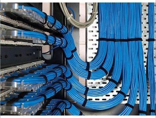
Good pathway design makes compliance easy to achieve and difficult to defeat during later changes. Half-round spools, waterfall drops, radius limiters, and rounded rack accessories provide a repeatable surface around which cable can be dressed. These components are particularly valuable in high-density cabinets, where a straight tray exit can otherwise become an acute bend at the vertical manager. Commercial radius units such as the ICC half-round spool design are intended to preserve controlled curvature across rack, wall, ceiling, and overhead applications.
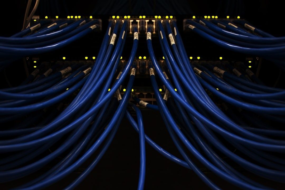
Bundle restraint must apply pressure without crushing the cable core. Hook-and-loop fasteners are generally preferable to aggressively tightened nylon zip ties because they can be adjusted as bundle size changes and are less likely to create localized compression. J-hooks should be spaced so that cable weight does not create a sag that transitions abruptly into a hook or wall penetration. Conduit entries should be aligned with the cable route, fitted with suitable bushings or edge protection, and sized to avoid forcing a full bundle through a narrow throat.
Lifecycle changes deserve the same attention as the initial installation. A rack can become noncompliant when additional patch cords, power whips, or fiber trunks are added years after commissioning. Preventive design should reserve pathway capacity, maintain access to radius-control hardware, separate power and data routes, and include labeled photographs or drawings. Standards-based administration, documented testing, and re-certification after major moves reduce the likelihood that a seemingly minor change creates a hidden physical-layer fault.
- Specify minimum radius values on drawings, installation method statements, and inspection checklists.
- Use waterfall transitions and rounded accessories at rack tops, bottoms, and side entries.
- Keep high-density copper bundles separated where alien crosstalk or heat can become a concern.
- Provide spare pathway capacity instead of designing every tray or conduit at its practical limit.
- Require visual inspection and test verification after moves, adds, and changes.
Build Cabling Infrastructure That Withstands the Test of Time
Poor bend management creates lifecycle costs that extend well beyond the original installation. A cable may pass initial acceptance testing yet develop intermittent errors after repeated moves, thermal cycling, or added bundle load. Troubleshooting then consumes engineering time, interrupts production, and can lead to unnecessary replacement of switches, optics, patch panels, or transceivers. Proactive pathway planning costs less than diagnosing an intermittent fault in a live data center, especially when access windows are limited.
Pre-commissioning should include a specification-first review of cable datasheets, radius calculations, pathway capacity, termination geometry, and test limits. Compliance audits should verify not only labels and topology, but also physical curvature at every transition. Treat cable radius as a core performance metric, alongside insertion loss, return loss, crosstalk, and attenuation. From datasheet to deployment, disciplined curvature control preserves signal margin, reduces lifecycle risk, and gives future technicians a network that remains fit for the application.
- Confirm manufacturer-specific dynamic and static radius requirements before installation.
- Inspect high-risk locations before ceiling closure, rack loading, or pathway handover.
- Certify copper and fiber using tests appropriate to the deployed application.
- Retest after significant changes and retain results with pathway documentation.