
Mitigating Thermal Buildup in High-Density Cable Trays: Derating Calculations and Spacing Strategies
On October 11, 2026 by lukasThe Physics of Heat Accumulation in Modern Structured Cabling
IEEE 802.3bt Type 4 Power over Ethernet has changed the thermal design problem in enterprise structured cabling. A Type 4 power-sourcing equipment port can provide up to 90 W at the source, with the powered device receiving less after cable losses. The practical implication is that high-power access points, PTZ cameras, displays, lighting controllers, and other endpoints can place a sustained electrical load on every conductor pair in the channel. A useful starting point is this guide to PoE power budgets and cable length, which explains how source power, cable resistance, voltage drop, and delivered device power interact.
Thermal accumulation follows the same basic electrical relationship that governs any resistive conductor: power converted to heat is proportional to I²R. As current rises, even a modest increase in conductor resistance can produce a disproportionately larger heat load. Hundreds of energized twisted-pair cables packed together can therefore create a warm central zone that cannot readily exchange heat with surrounding air. The consequences are not limited to temperature measurements. Sustained heat can accelerate dielectric aging, increase copper resistance and insertion loss, reduce available voltage at the powered device, and make polymer jackets or insulation less flexible and more vulnerable to damage.
A conventional tray fill percentage does not describe this thermal behavior. Two pathways can have identical physical fill while producing very different temperatures because of conductor gauge, cable construction, ambient conditions, power classification, bundle geometry, and airflow. A dense group of Type 4 cables in a 45°C plenum is a fundamentally different design case from a lightly loaded bundle in a conditioned telecommunications room. Thermal derating and deliberate spacing must therefore be treated as primary design inputs, not as corrections made after the tray has been filled.
Decoding NEC Table 725.144 and Ampacity Derating Rules
NEC Article 725.144 provides a framework for managing heating in power-limited circuit cables, including certain PoE applications. Its bundle ampacity table is based on assumptions that do not automatically match every telecommunications space. In particular, the table values use a 30°C ambient reference, while many cabling specifications and IEEE operating assumptions use a 45°C ambient with a permitted temperature rise. A design that applies a table value without correcting for actual ambient conditions can overstate the available thermal margin.
The correction process should begin with the cable datasheet and the installation environment. Confirm the conductor material, conductor size, insulation temperature rating, number of energized pairs, cable listing, and maximum continuous current. Next, determine the ambient temperature at the hottest point in the pathway, not merely the room set point. The effective conductor ampacity can then be temperature-adjusted using the applicable NEC correction method, commonly expressed through the relationship between the reference ambient, the conductor rating, and the actual ambient. The result must be checked against the expected current per conductor and the permitted bundle size.
Conductor gauge has a direct effect on the result. A 22 AWG conductor generally has lower resistance than a 24 AWG conductor of comparable material and length, while 23 AWG is often selected as a practical balance between thermal performance, flexibility, and termination compatibility. Lower resistance reduces both voltage drop and I²R heating. Bare copper is the appropriate baseline for standards-compliant high-power applications; copper-clad aluminum should not be substituted because its higher resistance can increase heating and compromise terminations.
| Design variable | Lower-risk approach | Thermal concern |
|---|---|---|
| Ambient condition | Design for the measured worst-case temperature | 30°C reference values may be insufficient in a 45°C plenum |
| Conductor size | 23 AWG or larger solid bare copper where compatible | Smaller conductors generally have higher resistance |
| Cable rating | 75°C or appropriately LP-rated construction | Temperature rating does not eliminate bundle derating |
| Bundle size | Smaller sub-bundles, often no more than 24 cables where guidance supports it | Large cores of tightly packed bundles retain heat |
| Spacing | Approximately 1.5 inches between sub-bundles in plenum applications where specified | Adjacent bundles reduce exposed surface area and airflow |
A practical calculation can be organized into five steps. First, establish the maximum current per conductor from the PoE class and the equipment design. Second, calculate or obtain loop resistance using conductor size, material, channel length, connectors, and operating temperature. Third, estimate cable loss with P = I²R and voltage drop with V = I × R. Fourth, apply the NEC bundle adjustment and ambient correction to the cable”s allowable ampacity. Finally, compare the calculated operating point with the cable”s listing and manufacturer installation instructions.
The calculation should use the complete channel rather than only the permanent link. Patch cords, connectors, equipment-side terminations, and elevated temperatures all contribute to the real operating condition. If the equipment uses a proprietary or non-IEEE power method, the current cannot simply be inferred from a standard PoE class. The source manufacturer must provide the electrical behavior, and the installation must be evaluated independently against applicable code requirements.
Pathway Architecture and Cable Tray Thermodynamics
Pathway construction strongly influences how quickly heat leaves a cable group. A solid-bottom tray provides mechanical support and helps prevent small cables from falling through, but its broad surface can restrict air movement beneath the bundle. A wire mesh basket exposes more cable surface to surrounding air and generally permits better natural convection. An open ladder tray offers the greatest opportunity for airflow, although cable support, bend control, separation, and protection from physical damage still require careful detailing. A useful background reference, the Authoritative Source on cable tray construction and types, helps distinguish the physical pathway options, but thermal suitability must be verified for the actual cable load and environment.
Standard physical fill rules, such as 40% or 50% tray occupancy, are primarily space-management limits. They do not guarantee acceptable conductor temperature. A pathway can remain below its nominal fill limit while holding a compact, high-power bundle with inadequate exposed surface area. For Type 4 remote powering, a lower working fill, greater separation, and more frequent transitions between sub-bundles may provide a safer design margin than maximizing available tray volume.
The center of a dense bundle is the most difficult region to cool. Outer cables exchange heat with the surrounding air, while inner cables transfer heat through neighboring jackets and insulation before it can reach the pathway boundary. This creates a thermal gradient and can produce a central temperature spike even when the tray air temperature appears acceptable. Ventilation also depends on pathway orientation, nearby obstructions, rack density, ceiling conditions, and whether the tray is installed in a plenum with limited air movement.
- Use open or ventilated pathways where the environment and mechanical requirements permit.
- Reduce working fill for continuously energized Type 4 groups rather than treating the tray”s maximum fill as the design target.
- Keep high-power PoE cables away from heat-producing electrical equipment and poorly ventilated ceiling pockets.
- Document the cable construction, ambient temperature, bundle dimensions, and spacing assumptions on the design drawings.
- Coordinate tray geometry with access for inspection, testing, and future cable additions.
Physical Spacing and Cable Management Strategies in Practice
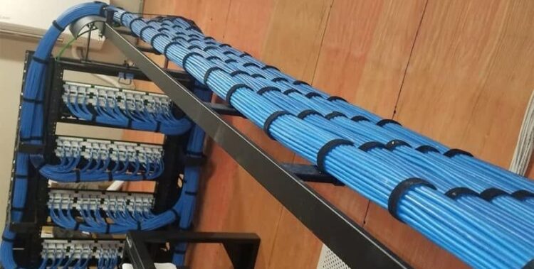
Physical management should be planned before cable pulling begins. The objective is not simply a neat installation. It is to create multiple small, stable groups with a high perimeter-to-area ratio, allowing heat to escape from a greater portion of the cable surface. Compartmentalized sub-bundles are usually easier to inspect and replace than one large bundle, and they make the assumptions used in ampacity calculations visible to the installation team.
- Map the expected Type 4 loads, cable lengths, pathway routes, ambient temperatures, and future growth allowance.
- Divide the pathway into sub-bundles sized for the calculated ampacity and the cable manufacturer”s installation guidance.
- Maintain clear air gaps between adjacent high-power groups, using the project specification where a defined separation is required.
- Secure each group with loose-fitting hook-and-loop fasteners that restrain movement without compressing the cable jacket.
- Verify bundle dimensions and spacing after installation, then record the result for commissioning and future maintenance.
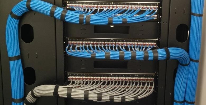
Tight nylon zip ties can create a hidden thermal and mechanical penalty. When cinched aggressively, they deform jackets, reduce the spaces between cables, and concentrate pressure at a narrow point. The result is less freedom for air movement and a greater risk of jacket indentation or conductor damage. Hook-and-loop fasteners provide controlled restraint and can be adjusted during moves, adds, and changes. They should still be installed firmly enough to prevent sagging, but not so tightly that they flatten the bundle.
Cable combing can improve visual order and simplify identification, but tightly aligned layers may reduce the air paths that would otherwise form between irregularly arranged cables. In an open tray, a carefully organized but breathable arrangement is preferable to a compressed rectangular block. Horizontal separation between adjacent high-power groups should be based on the applicable cable guidance and thermal calculation. Vertical separation, especially between stacked tray tiers, also matters because warm air rises and can preheat the pathway above. Where the design cannot provide adequate spacing, the specification should reduce bundle size or use a larger, more ventilated pathway.
Spacing should also be preserved at tray turns, riser transitions, firestopping points, and cabinet entries. These locations often become compression points because installers are managing bend radius and support at the same time. A thermally sound straight run can lose its benefit if several sub-bundles are forced through one small opening. Firestopping and penetration systems must be selected for the cable quantity and listing, while maintaining the required separation and bend-radius limits.
Selecting Cable Components and Jacket Materials for Longevity
CMP and CMR are installation classifications, not interchangeable indicators of thermal performance. CMP cable is listed for plenum spaces and uses jacket and insulation materials intended to meet the applicable flame and smoke requirements. CMR cable is listed for riser applications and may not be permitted in an air-handling plenum. Neither classification alone establishes the correct bundle ampacity or guarantees a particular operating temperature. The specification must consider the cable”s conductor size, 75°C rating where applicable, LP listing, DC resistance, insertion-loss performance, and manufacturer bundle instructions.
Shielded F/UTP construction can provide a conductive foil and drain path that assists electromagnetic control and may contribute to heat spreading, but shielding should not be treated as a substitute for derating or airflow. U/UTP cable can be fully suitable when its conductor size, temperature rating, category, and installation environment are appropriate. The selection should start with the electrical and environmental requirements, then assess shielding, grounding, termination, bend radius, and procurement constraints.
- Specify solid bare-copper conductors for permanent high-power links and verify resistance values.
- Prefer larger conductors, such as 23 AWG where compatible with hardware, when channel length and thermal loading demand additional margin.
- Confirm CMP or CMR classification against the actual space, rather than selecting jacket type solely from the cable category.
- Review continuous operating temperature limits and installation bend-radius requirements together.
- Reject CCA products for compliant high-power PoE designs because higher resistance increases voltage drop and heat.
Continuous exposure to elevated temperature can accelerate changes in polymer materials, including loss of plasticizer, hardening, cracking, and reduced recovery after bending. These effects may not appear during initial certification testing, yet they can reduce long-term mechanical integrity and make later moves or repairs more hazardous. Heat also increases insertion loss, while repeated thermal cycling can stress interfaces and terminations. The fit-for-application choice is therefore the cable that remains electrically stable, mechanically serviceable, and code-compliant throughout its expected lifecycle, not merely the cable with the lowest purchase price.
Building Resilient High-Power Infrastructure for Future Demands
Thermal planning for dense Type 4 PoE should be treated as an operational safeguard and a specification requirement. Fill percentages remain useful for pathway capacity, but they cannot replace ampacity calculations, ambient correction, cable-loss analysis, and physical spacing. A specification-first design connects the power budget at the switch to the conductor construction, channel length, bundle geometry, pathway ventilation, and worst-case room condition.
Before pulling cable, confirm the expected powered-device load, identify the hottest pathway locations, select compliant bare-copper cable, calculate bundle limits, and show sub-bundle spacing on the drawings. Provide installation teams with a clear fastening method and prohibit tight compression that invalidates the thermal assumptions. Commissioning should include channel certification, equipment power-budget verification, and inspection of the installed bundle geometry.
- Measure pathway temperatures during representative peak loading, not only during an empty or lightly loaded condition.
- Trend temperatures at dense tray sections, riser transitions, cabinet entries, and other likely heat traps.
- Recalculate capacity before adding substantial Type 4 loads or consolidating previously separate bundles.
- Inspect jackets, fasteners, bend points, and termination areas during scheduled maintenance.
- Maintain an as-built record showing cable type, bundle size, spacing, pathway construction, and test results.
These controls reduce lifecycle risk by preserving both power-delivery margin and data-transmission performance. They also make future expansion more predictable: additional ports can be evaluated against documented thermal capacity rather than guessed from remaining tray space. In high-density telecommunications environments, resilient infrastructure is built from the combined discipline of electrical calculation, pathway design, careful installation, and ongoing verification.