
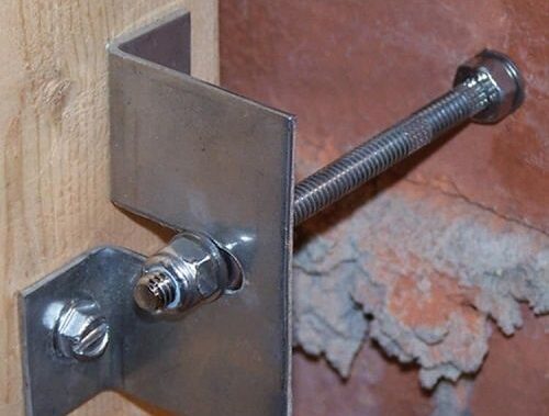
Tension vs Shear: Mechanical Anchor Selection in Solid Masonry
On November 12, 2026 by lukasRethinking Fasteners in Solid Masonry and Concrete Substrates
Post-installed mechanical anchors are often treated as interchangeable hardware because many products share similar diameters, thread forms, and installation tools. That approach is unsafe for structural work. An anchor is not selected by steel diameter alone. Its performance depends on the interaction between the anchor, the drilled hole, the surrounding substrate, the applied load, the installation process, and the available edge distance and spacing. For a defensible design basis, consult an Authoritative Source alongside product-specific evaluation data.
Solid masonry and reinforced structural concrete also behave differently. Concrete can provide relatively predictable compressive strength and, when properly characterized, a design basis for qualified anchorage systems. Unreinforced brick, stone, and other masonry units may contain variable joints, voids, bedding planes, and local defects that change the load path. A connection that appears adequate from an ultimate steel rating may fail when the surrounding material splits, cones out, pulls through, or spalls. Understanding the fundamental mechanics of an anchor bolt is therefore critical when calculating effective embedment depths and tensile breakout cones.
The specification-first process begins by identifying whether the governing action is tension, shear, or a combination of both. It then evaluates substrate compatibility, cracked or uncracked conditions, edge geometry, sustained loading, installation quality, corrosion exposure, and the applicable design standard. Steel capacity is only one limit state within that system.
Mechanics of Load Transfer Under Pure Tension
Under pure tension, a mechanical anchor transfers load into the substrate through friction, bearing, mechanical interlock, or a combination of these mechanisms. Torque-controlled wedge and sleeve anchors generate expansion as the nut is tightened. In a wedge anchor, the tightening action draws a wedge or expansion clip against the wall of the drilled hole. The resulting radial pressure creates friction and local bearing, allowing the anchor to resist withdrawal. Sleeve anchors use an expanding sleeve around the threaded shaft and generally offer greater tolerance across concrete, brick, and block applications, although their capacity is usually more dependent on the quality and strength of the surrounding material.
Several tensile failure modes must be checked independently. Steel failure occurs when the threaded shaft yields or fractures. Concrete breakout forms when a roughly conical region of concrete separates from the surface, typically with the cone size controlled by effective embedment depth and the anchor’s location relative to edges and neighboring anchors. Pullout or pull-through occurs when the expansion mechanism moves through the substrate without mobilizing a larger breakout volume. Splitting can occur when expansion forces act near an edge or in a narrow member. In masonry, local crushing, unit cracking, mortar-joint failure, and face-shell breakout can govern before the nominal steel rating is approached.
Embedment depth affects both the available mechanical engagement and the size of the potential tensile breakout boundary. Greater effective embedment can increase capacity when the substrate is sufficiently thick and sound, but it does not eliminate the need to check edge distance, spacing, and member thickness. Higher compressive strength generally improves concrete breakout and pullout resistance, but it does not justify applying concrete values to untested brick or stone. For a defensible design, use product-specific data and the governing design method rather than assuming that a stronger anchor automatically produces a stronger connection.
- Confirm the actual substrate, including concrete strength, masonry unit type, mortar condition, and the presence of voids or joints.
- Check steel tension, concrete or masonry breakout, pullout, splitting, and side-face failure where applicable.
- Verify effective embedment after accounting for fixtures, washers, drilling tolerances, reinforcement, and any unbonded length.
- Apply the manufacturer’s specified torque, installation direction, hole diameter, and minimum member thickness.
Shear Stress Dynamics and Edge Proximity Boundaries
Shear loading creates a different load path from tension. The anchor shaft may experience direct shear and bending, while the substrate is exposed to edge breakout, pryout, splitting, and localized bearing. Steel shear failure is relatively straightforward to identify, but it is not always the governing condition. An anchor installed close to a free edge can push a wedge-shaped portion of concrete or masonry out of the member. A short embedment or stiff fixture can also create pryout, in which the fixture and anchor act together to lever material away from the surface.
Edge distance and anchor spacing are therefore structural variables, not merely installation preferences. Product evaluation reports provide minimum and critical distances, reduction factors, and limitations for specific diameters, embedments, and substrate strengths. A technical data sheet for a wedge anchor may provide separate values for tension, shear, lightweight concrete, and steel-deck assemblies, along with recommended spacing and edge distances. Those values cannot be transferred to a different anchor family or to solid masonry without supporting qualification.
A lateral load applied through a stand-off bracket, base plate, or equipment frame is rarely a pure shear force at the anchor interface. The offset between the load line and the substrate creates a bending moment. One side of the anchor group may experience increased tension while the opposite side takes compression and shear. Localized spalling can begin around the loaded anchor, particularly where the fixture bears unevenly or where the hole is oversized. The connection should therefore be analyzed for simultaneous axial force, shear, and moment, not simply divided into independent single-anchor checks.
- Locate every anchor relative to free edges, construction joints, masonry joints, openings, and reinforcement.
- Resolve the applied force into direct shear, axial tension, and moment from fixture eccentricity.
- Check steel shear, concrete or masonry edge breakout, pryout, splitting, and combined tension-shear interaction.
- Use the actual edge distance only when the selected product’s qualified design data permits that condition. A smaller distance should not be accepted merely because a nominal calculation appears adequate.
Mechanical Anchor Tradeoffs Across Wedge Sleeve and Drop-In Profiles
Wedge anchors are generally the preferred mechanical option for heavy-duty fastening in solid, cured concrete when adequate embedment, edge distance, and installation access are available. They provide direct expansion and high capacity, making them suitable for structural supports, machinery, industrial racks, and safety-critical fixtures. Their performance is sensitive to hole diameter, hole cleanliness, concrete condition, installation torque, and the presence of cracks. They are not automatically suitable for solid brick, stone, or other masonry units simply because the anchor can physically be installed.
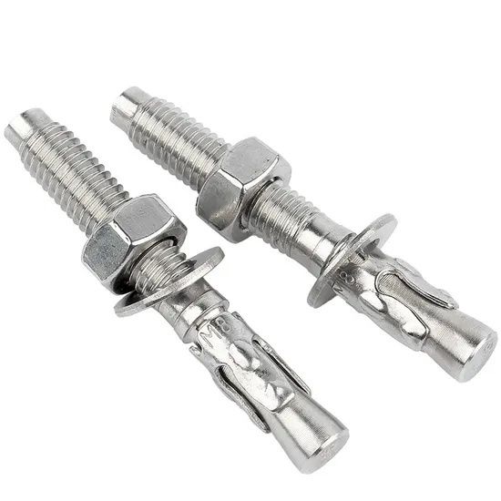
Sleeve anchors use a more distributed expansion sleeve and are commonly selected where broader masonry compatibility and installation tolerance matter more than maximum capacity. They can be suitable for handrails, frames, electrical equipment, and similar fixtures when the product data covers the substrate and load. Internal threaded drop-in anchors are installed into a predrilled hole and expanded internally, leaving a female thread for bolts or threaded rod. They can provide a neat, removable connection, but they require accurate drilling, controlled setting, sufficient base material, and a compatible installation tool. A drop-in anchor should not be specified for brick or stone unless the manufacturer has qualified that exact application.
| Anchor profile | Typical strength profile | Substrate suitability | Installation sensitivity |
|---|---|---|---|
| Wedge anchor | High tension and shear potential in qualified concrete | Best suited to solid, cured concrete; masonry use requires specific qualification | High sensitivity to hole diameter, embedment, torque, cracks, and edge distance |
| Sleeve anchor | Moderate capacity with broader application tolerance | Concrete, solid brick, and some block or masonry applications when covered by product data | Moderate sensitivity; substrate quality and expansion behavior remain critical |
| Internal threaded drop-in | Useful for removable threaded connections; capacity is product-specific | Normally selected for concrete; solid masonry and stone require explicit approval | High sensitivity to hole depth, cleaning, setting procedure, and thread engagement |
Material selection also affects lifecycle risk. Carbon steel may be suitable in controlled interior environments, while stainless steel is generally considered for outdoor, wet, or chemically aggressive conditions. Type 304 stainless steel may suit ordinary outdoor exposure, whereas Type 316 is more appropriate where chlorides or saltwater exposure create a higher corrosion threat. Corrosion resistance must be assessed alongside strength, galvanic compatibility, fire requirements, and the availability of qualified design data.
Dynamic Dead and Cyclic Loading Considerations
Sustained dead load and cyclic loading challenge an anchorage in different ways. A static equipment support may remain within its calculated strength limits while gradual substrate crushing, relaxation, corrosion, or loss of clamp force reduces reserve capacity over time. Vibration, impact, rotating machinery, traffic, wind reversal, or seismic action repeatedly changes the force direction and magnitude. Expansion anchors that depend on maintained radial pressure may be especially sensitive to cracking, hole enlargement, or repeated movement at the interface.
Micro-cracking can reduce the effective grip of an expansion mechanism and alter the shape of a tensile breakout region. In concrete, cracks may open under service or seismic actions, reducing breakout resistance compared with uncracked conditions. In masonry, pre-existing cracks, mortar deterioration, and unit variability can produce even less predictable behavior. A design should use an anchor qualified for cracked concrete when cracks are possible and should not treat an uncracked rating as a universal cyclic-load value.
Code compliance requires more than a favorable laboratory ultimate load. Evaluation reports and design software should be used within their stated limits, including concrete strength range, anchor diameter, embedment, edge distance, spacing, load type, and installation method. For example, qualified systems may be assessed under ACI 318 strength-design provisions and may include static, wind, or seismic applications, but the applicable tables and reduction factors remain mandatory. Comprehensive performance data, qualification criteria, and safety margins are governed by established evaluation standards such as ACI 355.2 (Qualification of Post-Installed Mechanical Anchors in Concrete), ICC-ES AC193 (Mechanical Anchors in Concrete Elements), and ICC-ES AC01 (Expansion Anchors in Masonry Elements), supplemented by literature reviews from the National Institute of Standards and Technology (NIST) on post-installed anchors under structural demands.
- Classify the load as sustained, intermittent, vibratory, impact, seismic, or load-reversing.
- Use cracked-concrete data where cracking is credible, and obtain project-specific engineering review for variable masonry.
- Check fatigue, serviceability movement, preload retention, corrosion, and fixture stiffness in addition to ultimate strength.
- Require product-specific evaluation reports, certified installation procedures, and documented inspection for safety-critical connections.
Design tools can help manage these interactions by analyzing base plates with axial force, shear, and moment in multiple directions. They are most useful when treated as calculation aids rather than substitutes for engineering judgment. The input must reflect the actual substrate and installation conditions, and the resulting report should identify the governing failure mode and all reduction factors.
Executing Defensible Anchor Specifications on the Jobsite
A defensible specification translates the structural model into field instructions that an installer can follow and an inspector can verify. The structural notes should identify anchor type, diameter, material, effective embedment, minimum edge distance, minimum spacing, substrate strength, allowable crack condition, washer and nut requirements, corrosion protection, and the required design standard. Where torque-controlled expansion anchors are used, the specified installation torque should be stated with the approved tool range and any restrictions on reuse or replacement.
Hole preparation is a primary part of anchor performance. The installer should use the specified bit diameter and drilling method, maintain the required hole depth, remove dust and debris, and avoid damaging the surrounding substrate. Holes should not be enlarged by uncontrolled movement of the drill. For internal threaded anchors, setting depth and full expansion must be verified with the designated setting tool. In masonry, the drilling mode should be selected to avoid unnecessary fracture, and installation locations should be kept clear of weak joints and visibly damaged units unless the design specifically accounts for them.
- Verify the substrate and layout before drilling, including edge distances, spacing, reinforcement, joints, and member thickness.
- Drill, clean, and inspect each hole according to the product installation instructions.
- Install anchors using calibrated equipment and record torque, embedment, anchor identification, and any rejected holes.
- Inspect the completed connection for cracking, spalling, slip, corrosion exposure, and fixture movement before commissioning.
- Establish periodic inspections for vibration-prone, fatigue-sensitive, outdoor, and load-reversing assemblies.
Long-term maintenance should be proportionate to consequence of failure. Equipment supports, safety barriers, suspended services, and structural frames deserve documented inspection intervals rather than informal observation. Any evidence of anchor movement, rust staining, cracked masonry, loose nuts, repeated vibration, or changed equipment loading should trigger engineering review. From datasheet to deployment, the safest selection is the one that remains fit for the actual substrate, load path, installation quality, and operating environment.